













Forged Flange for Wind Power Structures: Applications and Project Specifications
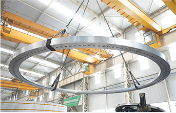
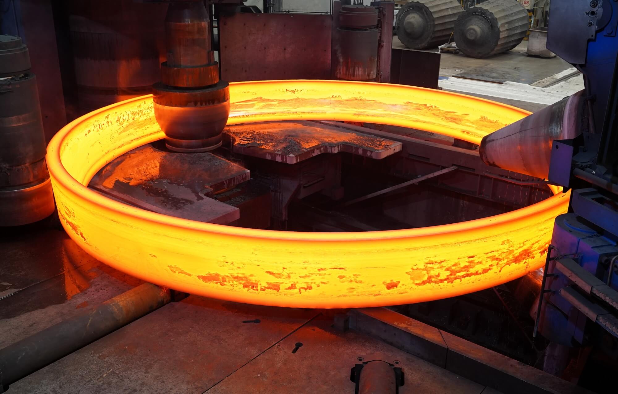
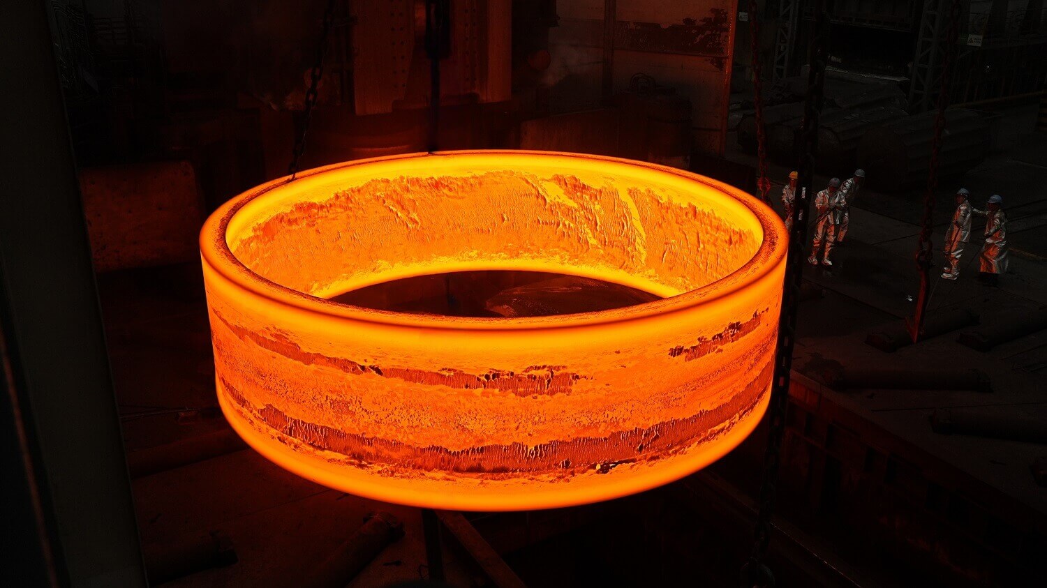
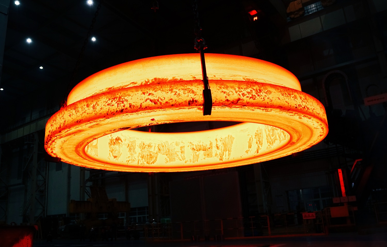
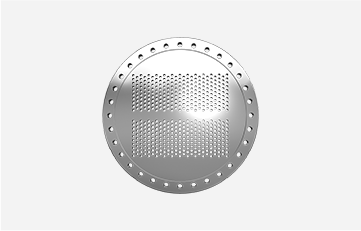
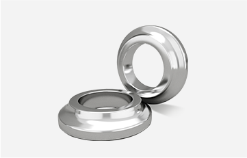
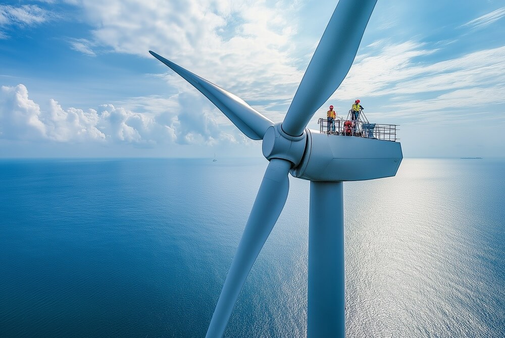
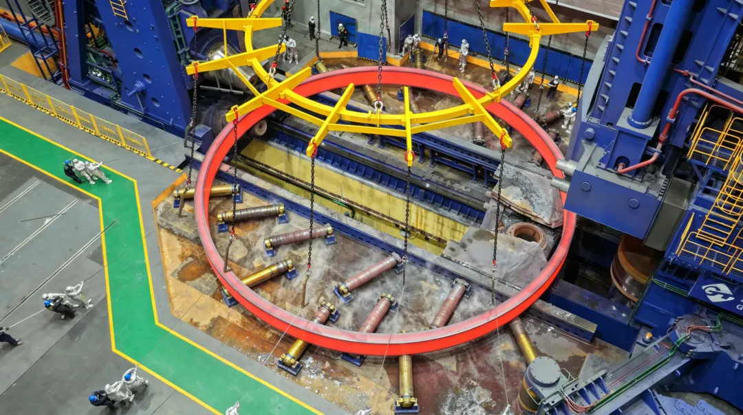
A forged flange for wind power structures is a ring-shaped connection component used in tower and foundation-related assemblies. The product range includes tower flanges, pile flange rings, top and bottom flanges, TP/MP flanges, and jacket flanges. Each is manufactured to the geometry and material requirements of its particular connection.
Iraeta has delivered wind power flanges up to 12 metres in diameter. Project references include 7.5-metre flanges for Dominion, 7.9-metre flanges for Moray West, 10-metre flanges for the Lianjiang offshore project, and 11.9-metre flanges for the CRRC Qihang Dongying prototype project.
The range combines large-diameter component manufacture with project quantities extending from prototype orders to several hundred flange pieces. Ring forming, thermal processing, and machining support the progression from the specified material to the supplied flange.
Structural Flange Applications in Wind Power
Tower flanges and pile flange rings form part of the structural component range. The wider portfolio includes top flanges, bottom flanges, TP/MP flanges, pile-leg flanges, and jacket flanges.
These products are distinct from the yaw and pitch bearing forgings, gears, and transmission shafts used elsewhere in the turbine. They are also separate from the drive rings, pile follower forgings, and slewing bearings supplied for installation vessels.
The forged wind power flange range therefore sits within a broader manufacturing portfolio while retaining a defined structural focus. Its relevant component characteristics include outside and inside diameters, section profile, axial height, connection faces, and machined features.
For tower-related components, the flange designation identifies its position within the assembly, while the drawing establishes the actual dimensions. For foundation-related products such as TP/MP and jacket flanges, the drawing likewise defines the connection geometry and supplied condition.
A circular form does not make these components interchangeable. A flange’s complete section and interfaces—not its outside diameter alone—identify the part required by the structure.
Project Specifications Across Different Turbine Platforms
Completed references cover projects in the United Kingdom, the United States, Spain, and China. The following examples combine flange diameter with turbine model and supplied quantity.
| Project or product reference | Location | Turbine model | Flange diameter | Quantity |
| Moray West Offshore Wind Project | United Kingdom | SGRE 14 MW | 7.9 m | 152 pieces |
| GE Haliade-X 14 MW | Spain | GE 14 MW | 7.5 m | 60 pieces |
| Dominion Project | United States | SGRE 14 MW | 7.5 m | 83 pieces |
| China Resources Lianjiang Offshore Project | Fujian, China | DEC 18 MW | 10 m | 390 pieces |
| CRRC Qihang Dongying Prototype Project | Shandong, China | CRRC 25 MW | 11.9 m | 14 pieces |
| Three Gorges Zhangpu Liuao Phase II Offshore Wind Project | Fujian, China | DEC 13 MW, Goldwind 14.3 MW, Goldwind 16 MW | 8 m | 154 pieces |
All quantities are flange pieces rather than turbine counts.
Project Range and Component Diameter
The references span several turbine platforms and flange diameters. The two SGRE 14 MW references use different stated diameters: 7.9 metres at Moray West and 7.5 metres at Dominion. The GE Haliade-X reference also lists 7.5-metre flanges, with a different project quantity.
Turbine power rating is consequently an equipment reference, not a complete flange specification. The component still requires its own drawing, material definition, and connection geometry.
The 8-metre Zhangpu Liuao reference lists three turbine models within the project entry. The 154-piece total belongs to that reference as a whole; it is not a model-by-model allocation.
Large-Diameter and Multi-Piece Supply
The Lianjiang reference combines a 10-metre diameter with 390 pieces. The Dongying prototype reference identifies a larger diameter of 11.9 metres and a quantity of 14 pieces.
These represent different supply profiles. One involves a larger stated piece count; the other records a flange diameter close to the maximum delivered size.
The figures establish diameter and quantity without defining every technical characteristic. Material grade, section dimensions, individual weight, and connection position are not included in these project summaries. Those remain part of the component specification rather than assumptions derived from the turbine model.
The wind power application portfolio brings these structural flange products together with other turbine components, supported by manufacturing bases in China and Spain.
Twelve Metres Delivered, Twenty-One Metres Processable
The maximum delivered flange diameter is 12 metres. The maximum processable flange diameter is 21 metres.
The first figure records completed supply. The second describes processing capability available for evaluating larger proposed components.
The 11.9-metre Dongying reference is a named project example near the delivered limit. The 21-metre figure is not a record of a completed wind power flange of that diameter.
For a proposed component, the manufacturing envelope includes more than outside diameter. Inside diameter, height, section profile, material, and required machining establish the actual workpiece. Two flanges with the same outside diameter can have different sections and substantially different manufacturing scopes.
This distinction is relevant during design development. A large processing diameter provides room for reviewing new geometries, while the accepted manufacturing proposal defines the specific component to be supplied.
Ring Forming and Machined Flange Geometry
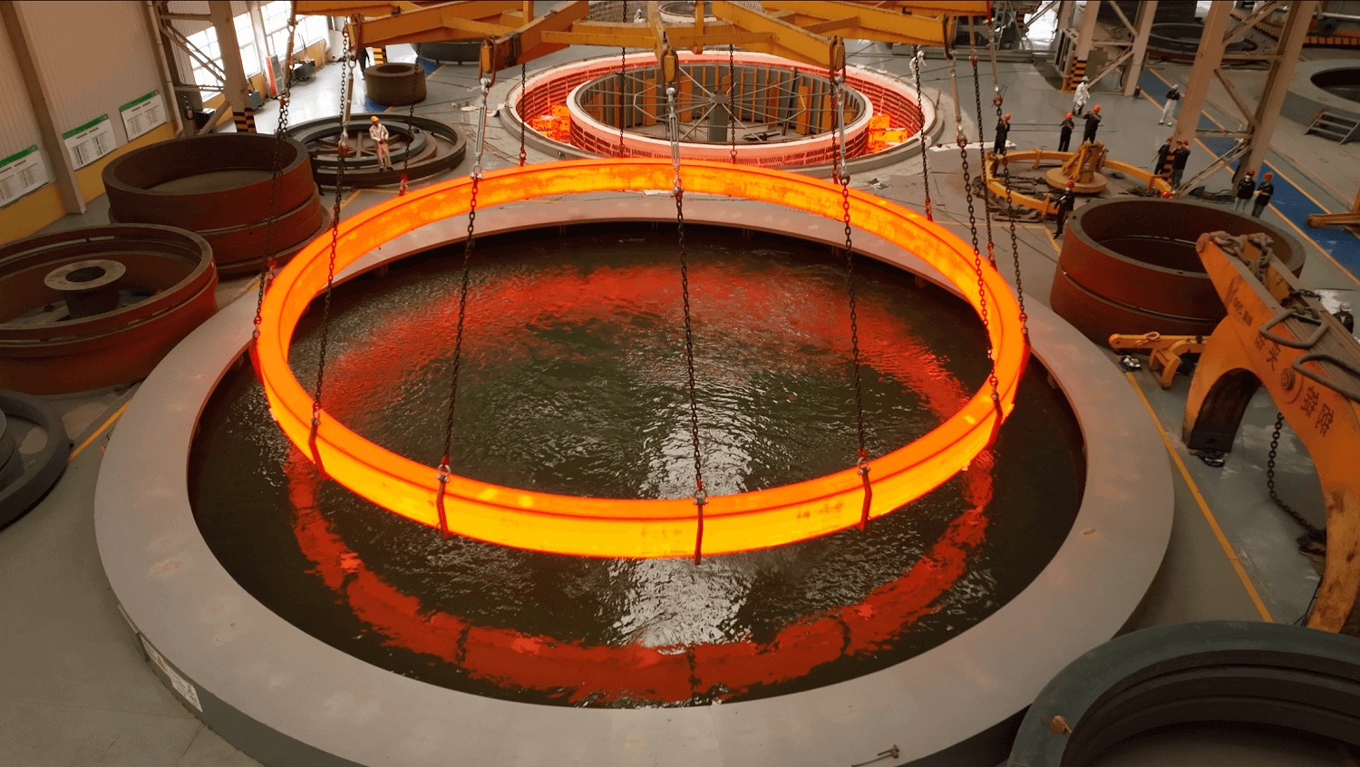
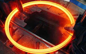
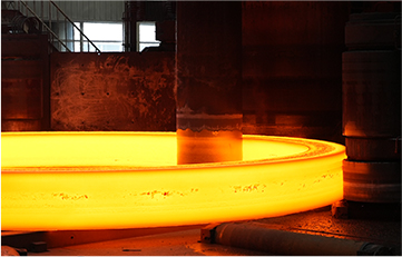
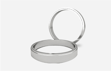
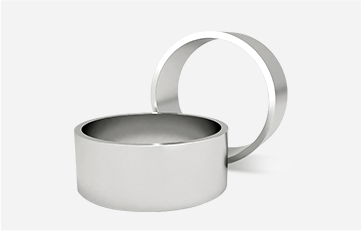
The manufacturing range includes rectangular-section and complex-profile ring forgings. This provides options for forming a ring body suited to the component geometry before completing the agreed machining operations.
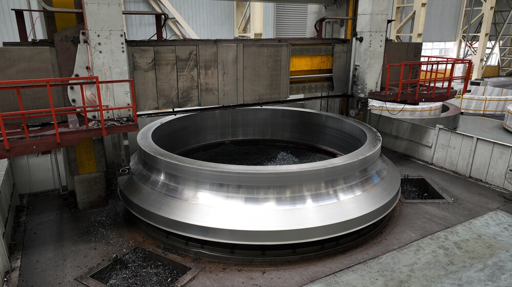
For a structural flange, the section drawing connects the overall ring dimensions with its connection features. The forming scope establishes the supplied forging shape; machining produces the faces and features included in the finished or intermediate component.
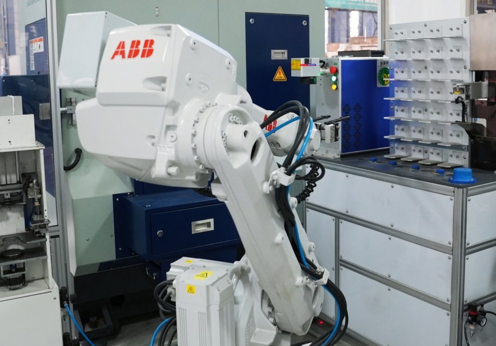
Available large-ring forming and machining services include CNC cutting, grinding, and drilling. The machining scope follows the component drawing and the stage at which the flange will be delivered.
A finish-machined flange includes the drawing operations and dimensional requirements covered by the order. An intermediate supply may retain allowances or leave specified operations for subsequent manufacture. The quotation and supply drawing establish that boundary.
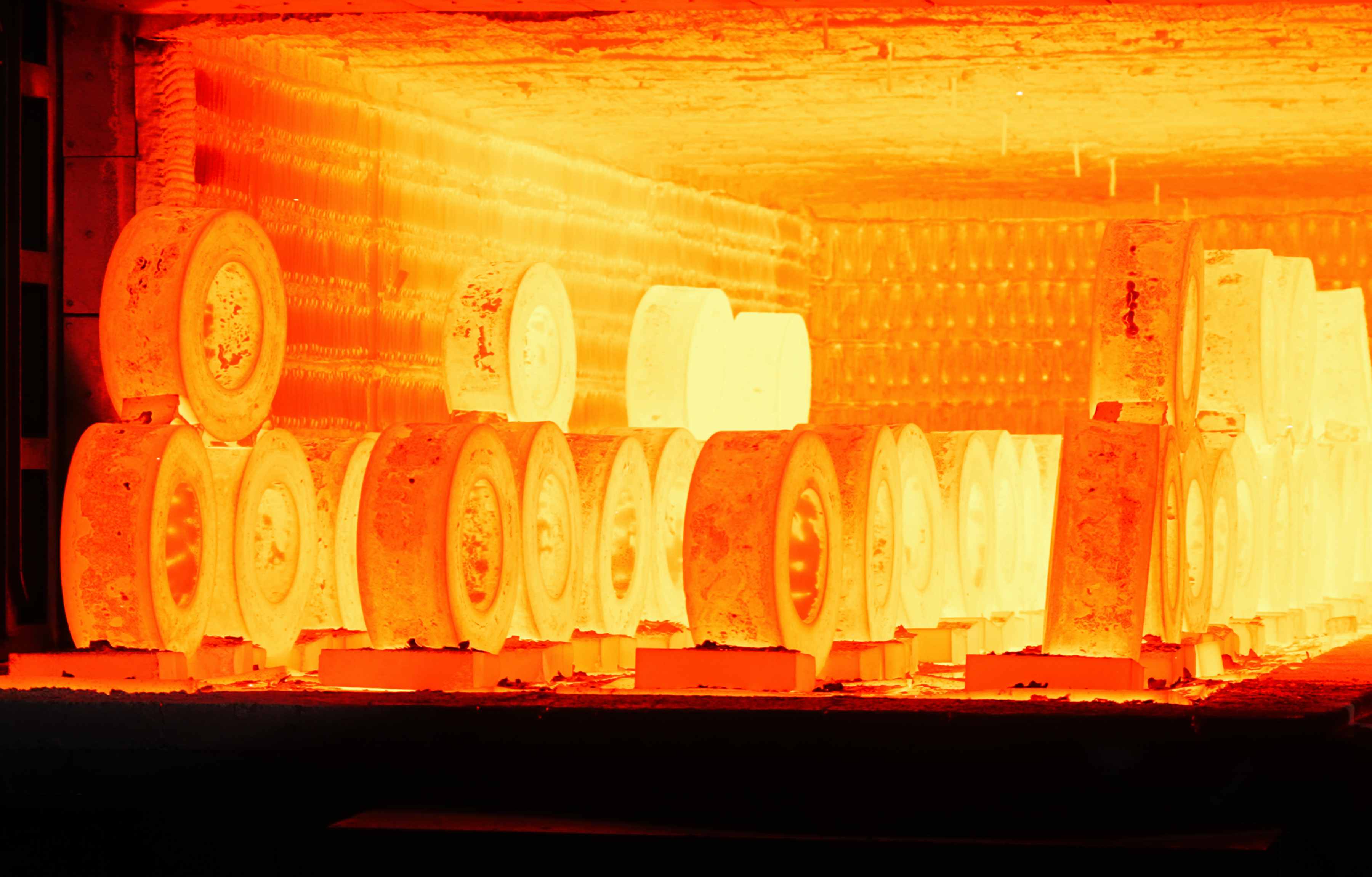
Thermal processing is integrated with the material requirement. Available treatments include normalizing, tempering, quenching and tempering, annealing, solution treatment, stress relief, and other combinations.
No single treatment is implied by the term “wind power flange.” The steel grade, thermal condition, required properties, and acceptance requirements form a coordinated component specification.
Manufacturing Resources in China and Spain
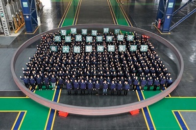
Iraeta operates eight wind power flange production lines in China and two in Spain. The two-country manufacturing footprint supports its international wind power business and project deliveries.
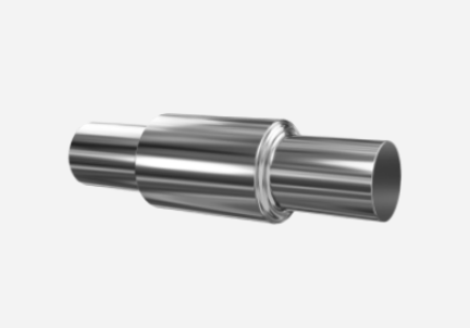
The product range extends beyond structural flanges to yaw and pitch bearing forgings and gearbox forgings. Installation-equipment components include slewing bearings, drive rings, and pile follower forgings. Floating offshore wind mooring chains are also included in the wider supply portfolio.
This breadth connects several parts of the wind power equipment chain while keeping their manufacturing roles separate. Structural flanges serve tower and foundation-related requirements; installation-vessel components support offshore construction; bearing and gearbox forgings belong to other equipment assemblies.
International service resources also include partner GRI’s factories and networks across Europe, the Americas, Asia, and Africa. These resources support discussions with turbine OEMs and EPC contractors about regional supply requirements.
The completed flange references reflect that international scope, with projects in the United Kingdom and United States alongside product and project references in Spain and China.
Steel Recycling and Lower-Carbon Production
Material sourcing and production processes form another part of wind power flange manufacture.
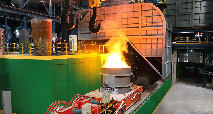
Most raw materials are sourced from the company’s own short-process steel mills. Production leftovers are recycled, returning material to the steelmaking cycle. Scrap recycling is combined with manufacturing measures including hot charging of raw materials and oxy-fuel combustion.
These measures address different stages of production. Recycling concerns material circulation, while hot charging and combustion technology concern processing. Together, they form part of the company’s lower-carbon manufacturing approach.
For projects with environmental reporting requirements, product-specific carbon information belongs alongside the technical supply package. The manufacturing measures described here do not establish a numerical carbon footprint for every flange or project.
This keeps environmental information connected to the actual product without replacing the material, dimensional, and quality requirements of the structure.
Project-Specific Wind Power Flange Supply
Wind power structural flanges range from tower-related products to TP/MP and jacket flanges. Their geometry follows the connection design, and their manufacturing scope combines material, forming, thermal processing, and machining.
The delivered references span 7.5- to 11.9-metre flanges across several turbine platforms, including a 390-piece reference for Lianjiang and a 14-piece prototype reference for Dongying. The maximum delivered diameter of 12 metres remains separate from the 21-metre processing capability.
Iraeta combines these project references with ring manufacturing resources in China and Spain. For a new structure, the component drawing and technical specification provide the basis for reviewing geometry, supplied condition, quantity, and delivery requirements.
To discuss a forged flange for wind power structures, contact the team with your project drawings, or send the available specification and delivery schedule to ebiz@iraeta.com.


Recommended reading
Unlocking the Secrets of Forging: The Performance Code of Classic Processes
Must-Read for Ring Forging: Advantages and Applications of the Forge-Rolling Process
Open-Die Forging vs. Ring Rolling: Helping You Choose the Optimal Forging Process