





















Carbon Steel Forged Flange: Material, Manufacturing and Ordering Requirements
A carbon steel forged flange is specified by its material grade, connection geometry, required thermal condition, and finished dimensions. For an industrial piping project, these requirements form a single component specification: the material and processing establish the required properties, while the drawing defines the interfaces and features supplied for installation or further manufacture.
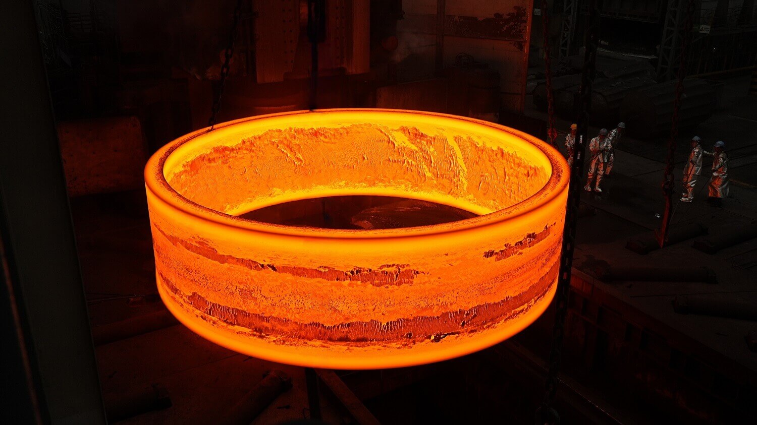
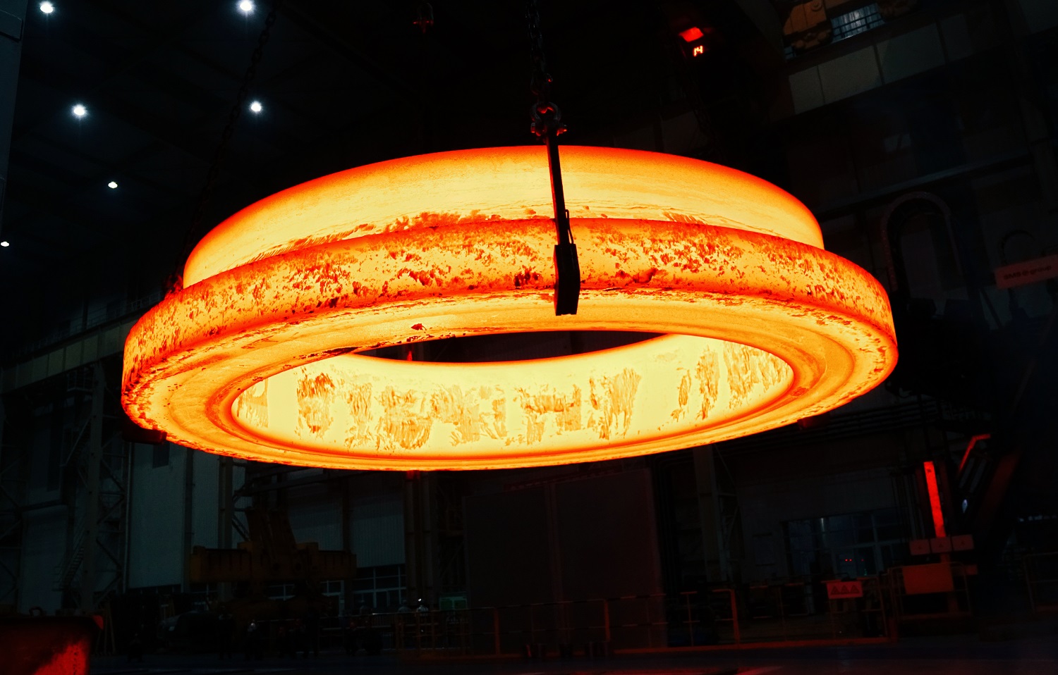
Iraeta manufactures pipe flanges for petrochemical, energy, and industrial piping applications. Its pipe flange product range lists outside diameters of 73–3,000 mm and individual weights of 0.3 kg–4 tons. The published range provides a starting point for reviewing a proposed component; the available carbon steel grade, section geometry, and delivery condition remain subject to the specific manufacturing proposal.
For procurement and engineering teams, the central task is to keep the material, drawing, manufacturing scope, and acceptance requirements aligned from technical review through delivery.
1.Material Grade and Drawing Requirements
The material specification identifies the steel grade, required delivery condition, and any supplementary project requirements. The flange drawing defines the section geometry, connection details, dimensions, and tolerances, with its revision referenced in the order documents.
These documents work together. A drawing may refer to a separate material specification, while the purchase specification may contain additional inspection or documentation requirements. The accepted supply package preserves those references so that manufacturing and inspection follow the same requirements.
For orders containing several flange items, each item has its own material and drawing references. Differences in grade, section dimensions, machining scope, or required condition remain visible at item level rather than being absorbed into general order notes.
| Specification element | Defined requirement |
| Material | Steel grade, governing material document, and supplementary requirements |
| Component geometry | Applicable flange standard or approved drawing |
| Drawing status | Drawing number, revision, and approval status |
| Thermal condition | Required condition at delivery |
| Machining scope | Completed surfaces, features, and any retained allowances |
| Acceptance | Inspection methods, criteria, and required records |
During design development, some requirements may still be awaiting approval. Keeping those points separate from released requirements allows technical discussions to continue without treating a preliminary proposal as an approved manufacturing instruction.
Any proposed material substitution or drawing change belongs in the technical approval process. Its acceptance needs to be reflected in the final order documents, not left only in correspondence.
2.Flange Geometry and Connection Details
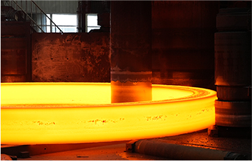
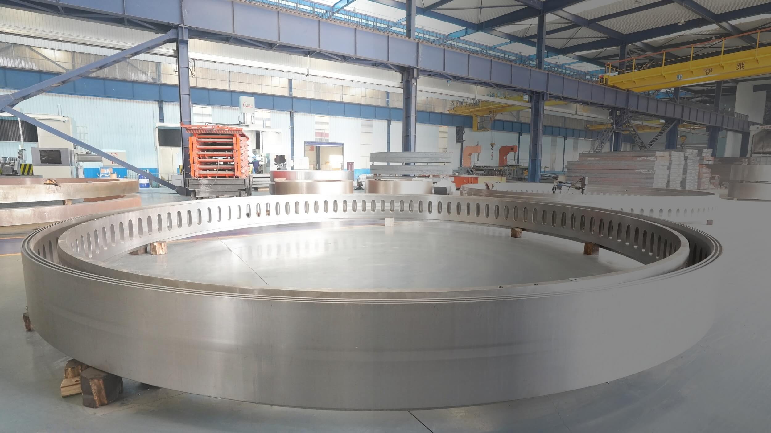
The outside and inside diameters establish the main ring dimensions. Axial height, section profile, connection faces, and local features complete the geometry and define the work included in forming and machining.
The section drawing is particularly important for components with changes in thickness or profile. It connects the overall workpiece dimensions to the local features inspected at delivery. Two flanges with the same outside diameter can therefore represent different manufacturing scopes.
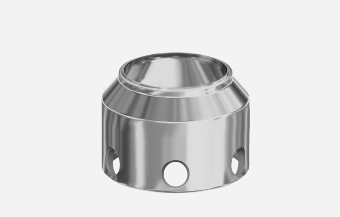
Connection details also remain application-specific. The geometry discussed in forged flanges for wind power structures includes diameters, axial height, section profiles, connection faces, and machined features. These structural products belong to a separate application from pipe flanges; their dimensions and project references do not establish carbon steel pipe-flange availability.
For piping components, the applicable standard and approved drawing define the required interfaces. Any project-specific departures remain identifiable in the technical package.
The relationship between the drawing and the supply stage matters as well. A final component drawing describes the finished part, while an intermediate-supply drawing identifies the condition accepted before subsequent operations. Using the appropriate drawing for each stage prevents unfinished features from being confused with completed requirements.
3.Heat Treatment and Required Material Properties
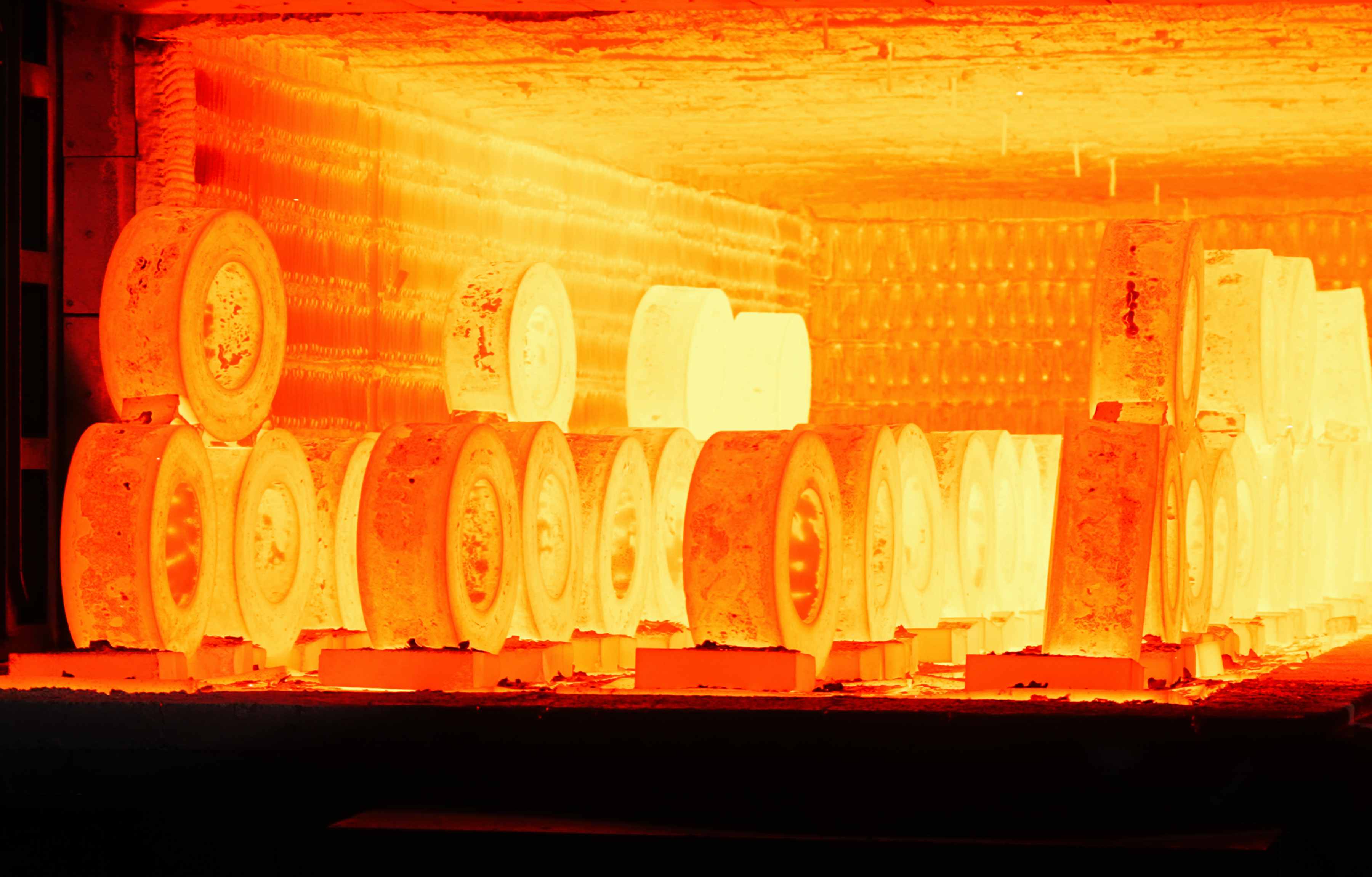
Heat treatment influences the mechanical properties of a forging. The selected treatment depends on the material and acceptance requirements of the component rather than on the product name alone.
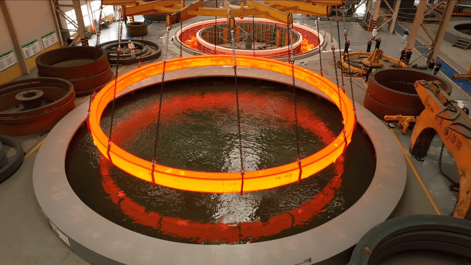
Iraeta’s forging, heat-treatment, and machining services include normalizing, tempering, quenching and tempering, annealing, stress relief, and other treatments for different materials and applications. The selected route for a carbon steel forged flange follows the specified grade, required properties, and agreed delivery condition.
The thermal condition remains consistent across the material specification, manufacturing proposal, and acceptance documents. Where the project requires supporting records, those records form part of the agreed documentation package.
A proposed alternative treatment requires the same technical attention as a proposed material change. It may affect the relationship between the processing route and required properties, so it cannot be treated only as an internal scheduling choice.
Generic furnace temperatures and holding times do not define the acceptance requirements of every flange. Unless a project specifies a particular processing requirement, the purchasing documents can focus on the required material condition, properties, and evidence of conformity. Detailed process commitments then remain tied to the approved manufacturing scope.
4.Machining Scope and Delivery Condition
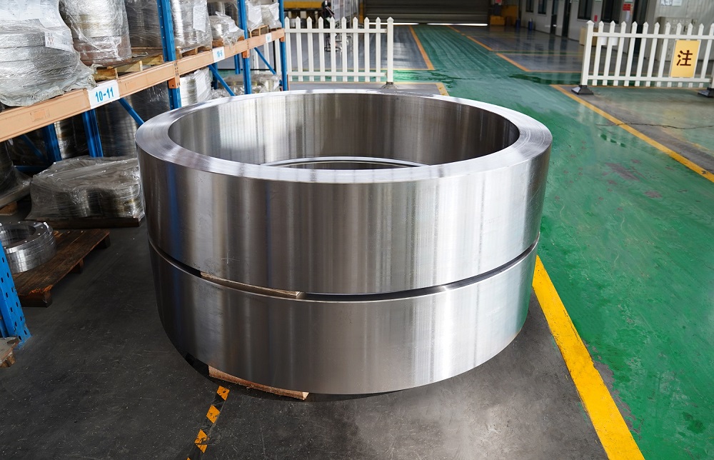
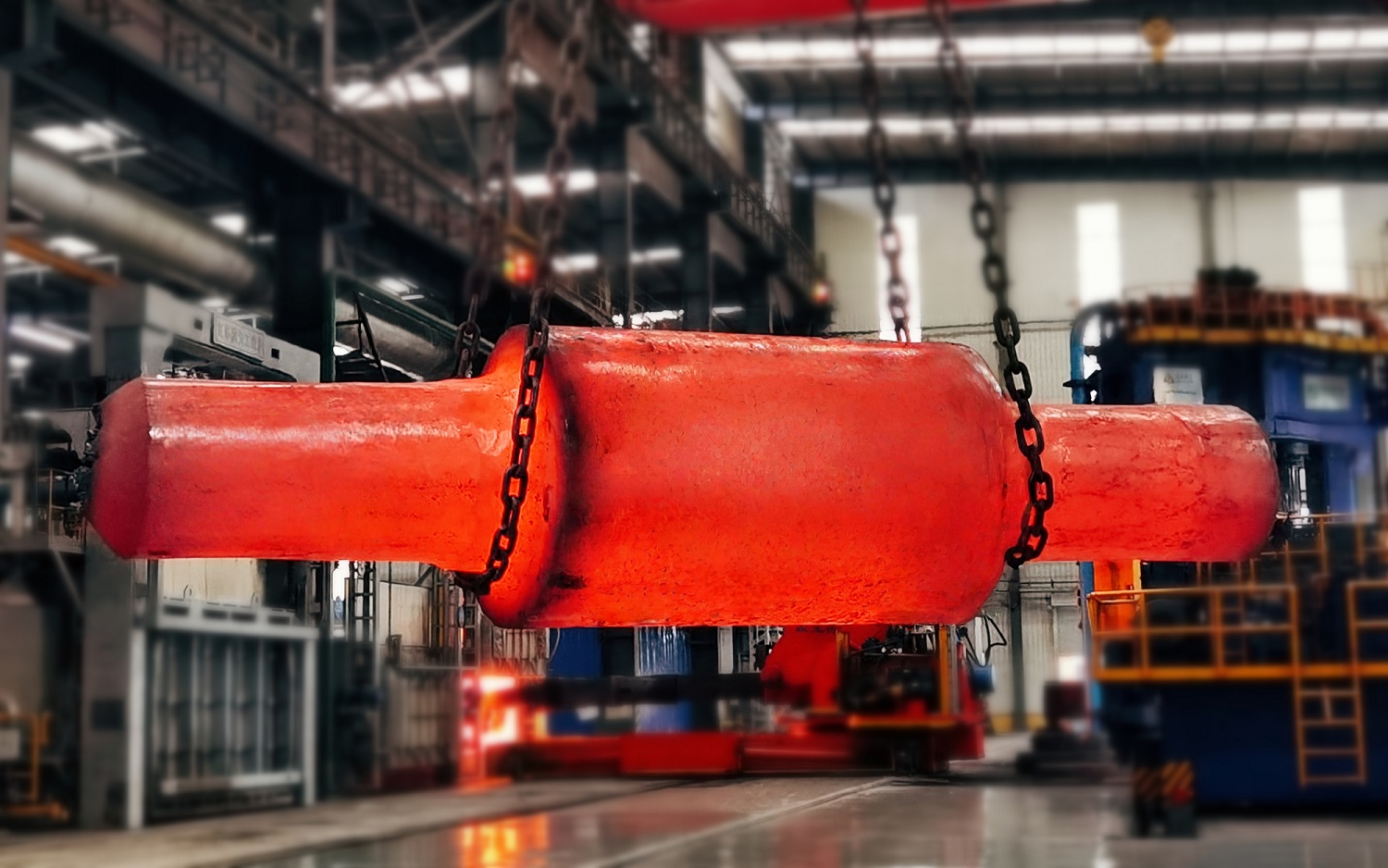
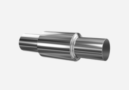
The machining boundary determines how much work remains after delivery. A forging supplied for further manufacture, a partly machined flange, and a flange supplied to an agreed final drawing represent different products for commercial comparison.
The manufacturing services described on the company’s forging page include CNC-supported cutting, grinding, and drilling. These resources support component manufacture, while the order drawing establishes the operations and dimensional requirements included in the supply.
For an intermediate component, the agreed drawing identifies retained allowances and unfinished surfaces or features. For a finish-machined component, it identifies the drawing requirements covered by the order.
| Delivery condition | Scope established in the agreed documents |
| Forging for further manufacture | Supplied shape, thermal condition, and remaining operations |
| Partly machined flange | Completed surfaces, retained allowances, and unfinished features |
| Finish-machined flange | Included drawing operations, dimensional requirements, and inspection scope |
This distinction becomes especially important when another workshop completes the component. Its requirements need to be reflected in the intermediate drawing so that the received forging matches the next manufacturing stage.
The same boundary applies to inspection. Dimensions accepted on an intermediate component are not automatically the final assembly dimensions. The inspection report and drawing reference identify the actual supplied condition.
5.Dimensional Control and Batch Consistency
For multi-piece orders, conformity concerns both individual components and consistency across the batch. Each flange remains subject to its specified requirements, while item identification connects the component to the relevant manufacturing and acceptance records.
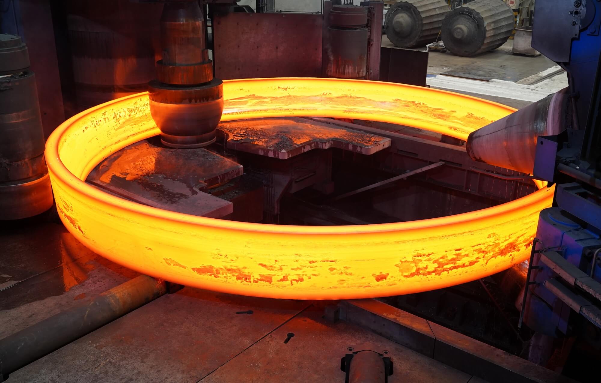
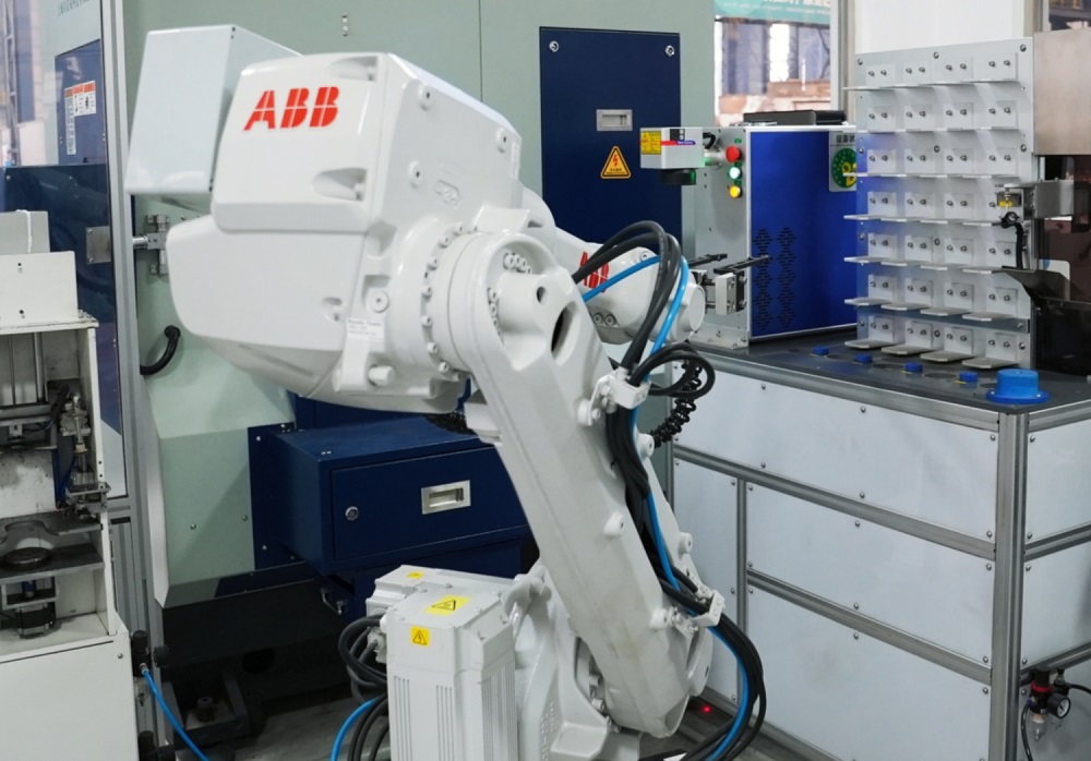
The pipe-flange manufacturing system described by the company includes intelligent forging lines, control of dimensional accuracy and batch consistency, and adjustment of production-process parameters. The product page also identifies automatic die-forging lines and five-axis machining centers.
These resources provide manufacturing context, but the drawing still governs the dimensional requirements of the order. Tolerances, reporting points, and inspection stages correspond to the component being supplied.
Where an order includes several sizes or revisions, the item list provides the link between quantities, drawings, and delivery batches. Maintaining that relationship is more useful than treating the order as a single combined tonnage.
For repeated components, the accepted drawing revision also remains consistent across production and documentation. Any approved change identifies the affected items so that earlier and later requirements are not mixed within the delivery.
6.Inspection and Documentation
Inspection requirements define how the supplied flange will be assessed. The relevant methods, acceptance criteria, reporting obligations, and customer involvement belong in the agreed technical scope.
Material documents establish the specified material reference. Dimensional records relate to the supplied drawing and condition. Any required testing follows the project’s stated methods and acceptance criteria.
| Review area | Required agreement |
| Material conformity | Material records and their governing references |
| Thermal condition | Required condition and supporting records |
| Dimensions | Drawing revision, tolerances, and reporting scope |
| Inspection and testing | Methods, acceptance criteria, and reports |
| Identification | Connection between the component and its documentation |
| Customer involvement | Review, witness, or release stages included in the order |
The depth of documentation follows the project requirements. A particular test, report, or customer-attendance stage is not automatically included simply because the component is described as a forged flange.
Certification requirements also need to be specific. Where a project requires an approval, the applicable certificate is reviewed against the relevant entity, manufacturing location, scope, and validity. A company-level certification does not, by itself, establish acceptance of an individual component.
7.Production Capacity and Order Scheduling
The published pipe-flange range includes annual output of 80,000 tons and five pipeline-flange and ring-rolling production lines. These figures describe the scale of the manufacturing operation, alongside the stated outside-diameter and individual-weight ranges.
Order scheduling depends on the actual supply package. Material, geometry, processing, machining, inspection, quantity, and required delivery dates all belong in that review. Annual output does not establish an available production slot or a committed lead time.
| Published product information | Order-specific review |
| Outside diameter: 73–3,000 mm | Complete section, material, and machining requirements |
| Individual weight: 0.3 kg–4 tons | Weight of the specified component |
| Annual output: 80,000 tons | Production allocation and order schedule |
| Forging and machining resources | Agreed processing route and supply boundary |
Phased deliveries require item quantities and dates for each batch. This gives the manufacturer a basis for discussing the actual project sequence rather than only the total order volume.
Technical approval milestones also belong in the schedule discussion. Where drawings or specifications are still under review, their release status remains visible alongside the required delivery date.
8.Commercial Comparison and Delivery Responsibilities
Quotation comparison is most meaningful when the technical scope is equivalent. Material references, drawing revision, heat treatment, machining, inspection, and delivery arrangements all contribute to the supplied value.
An excluded machining operation or inspection activity changes the comparison. So does an alternative material or a qualification attached to the proposed schedule. These differences need a clear approval status before the commercial decision is finalized.
The pipe-flange service scope includes technical coordination, standards compliance, production scheduling, packaging, logistics, and export procedures. The accepted quotation establishes which responsibilities are included for the individual order.
A compact comparison record captures:
Confirmed material and drawing references.
Proposed thermal and machining condition.
Included inspection and documentation.
Technical deviations and their approval status.
Delivery schedule and its conditions.
Packaging, transport, and export responsibilities.
The final purchase package brings the accepted quotation, drawings, specifications, and approved deviations together. Engineering, procurement, and manufacturing can then work from the same definition of the component and its delivery requirements.
9.Project-Specific Carbon Steel Forged Flange Supply
A carbon steel forged flange order connects material properties with component geometry, manufacturing scope, and acceptance requirements. The specified grade and thermal condition define the material requirement; the drawing and machining scope define what arrives; the inspection package establishes how conformity is recorded.
Iraeta supports pipe-flange discussions within its published manufacturing range. To review a proposed component, contact the team with your flange drawing and technical requirements, including the material specification, quantity, delivery condition, and project schedule. These documents provide the basis for discussing manufacturing details and agreeing on the supply scope.


Recommended reading
Unlocking the Secrets of Forging: The Performance Code of Classic Processes
Must-Read for Ring Forging: Advantages and Applications of the Forge-Rolling Process
Open-Die Forging vs. Ring Rolling: Helping You Choose the Optimal Forging Process